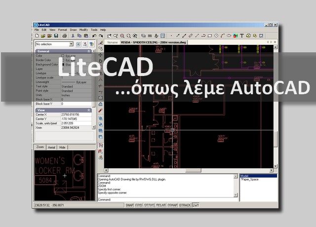
All the tools necessary to create drawings are in easy reach via drop down menus, toolbar icons or right click pop up menus making the LiteCAD.exe interface simple to use. As mentioned in our discussion of the interface, the black area in the figure above is termed the drawing editor (aka model space) and it is here that designs are created using tools selected from menus or toolbars.
Is located in Hoogeveen, DRENTHE, Netherlands and is part of the Architectural Services Industry. Has 91 employees at this location and generates $9.24 million in sales (USD). There are 3 companies in the Litecad B.V. Corporate family.
- PadCAD Lite is an easy to use free CAD application designed for small to medium sized projects such as home additions, remodeling projects, cabinetry work, and site surveys. With PadCAD Lite anyone can produce clean, clear CAD drawings. If you want to save or export your drawings to a professional C.
- The figure below shows a more complex design in model space. The drawing happens to be a landscape design, but LiteCAD.exe can be used to construct CAD drawings in any discipline. Note that a compound symbol (aka block) has been selected and the details about the block properties are shown in the Properties panel at the left.
Free Cad Symbols
Tip: We have changed the background color in the movie that follows. We show how to reset the background color at the end of the movie.
Sample design
The figure below shows a more complex design in model space. The drawing happens to be a landscape design, but LiteCAD.exe can be used to construct CAD drawings in any discipline. Note that a compound symbol (aka block) has been selected and the details about the block properties are shown in the Properties panel at the left.
Graphic tools

Point tool
A point is a single entity with a fixed coordinate position. Points are known as nodes and it is possible to snap (entity snap) and join (say) the end point of a line to a point. So points are often used as location markers for placement of other entities
Using Format>Point Styles enables users to change the size and appearance of the point style marker.
Line tool
Selection: Graphic > Line

Operation: Click with the left mouse button, that sets the start point of the line. Move away ready to indicate the end point for the line. The length and angle of the proposed line shows at the cursor. It is not possible to type pairs of coordinates for either the start or end point of the line. If precise coordinate positioning is required, we suggest drawing a line in its approximate position, select it and change its properties (X,Y values) after placing the line.
Polyline tool
The Polyline command is used to draw complex lines - a single entity consisting of a number of line segments. Various editing functions can be applied to polylines making them a valuable design tool. In landscape design work, they are commonly used to delineate areas of ground cover planting and areas requiring hatching such as paths and decking, but are also useful when creating your own symbols. The area covered by a closed polyline is automatically calculated in the Properties box to left of screen.

Someone with a proven track record of 25 years in the European field is guaranteed to know the quickest route to succes. This route starts with dedicated communication, namely direct and open contact with the client, from introduction to handover. Thanks to this approach, a compact and multidisciplinary team is able to deliver customized work as standard, even when interim modifications are required.
Personal and direct contact guarantees
short lines and solution focussed work
Litecad Alternative
Litecad's services are distinguished by key factors such as quality & cost awareness, thereby guaranteeing highly favourable rates. And the one factor that certainly shortens the route to success is Litecad's ability to fill in key positions at each level throughout the business chain at precisely the right moment. An approach that sets Litecad apart.