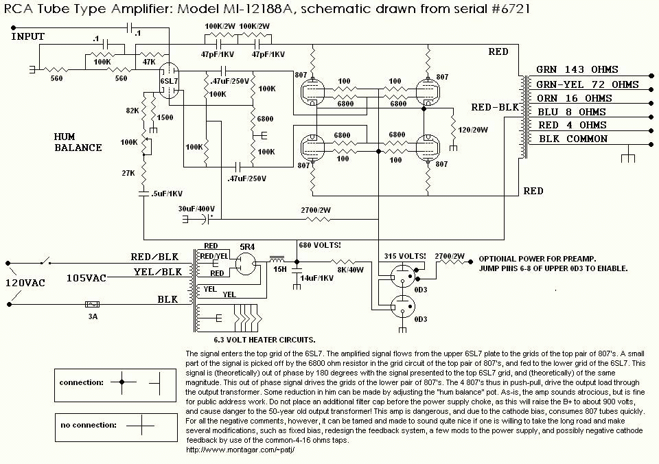
- 807 Tube Audio Amplifier Schematic Amplifier
- Tube Amplifier Schematics
- Audio Amplifier Schematic Diagram
Tags: 807, amplifiers, handbuilt tube amplifier, single-ended, tube amplifiers, tubes, vintage electronics 4 thoughts on “ Single-Ended 807 Amplifier ” Monte on March 17, 2018 at 3:09 am said. Tube Amp Schematics. Dc Circuit Circuit Diagram Diy Electronics Electronics Projects Amp Settings Valve Amplifier Crafts Science. An illustration of an audio speaker. An illustration of a 3.5' floppy disk. An illustration of two photographs. An illustration of a heart shape Donate. An illustration of text ellipses. An icon used to represent a menu that can be toggled by interacting with this icon.

A mighty 807parallell CFB push-pull amp
Here we have something encouraging, namely young bright guy that wants a tube amp and takes the challenge with his friends that he'll build one from scratch. His work helps him, since they just have declared that all tubes are redundant and there seems to be quite a stock of 807 and 6SN7 and 6SJ7 and OD3 tubes available for servicing. ( They serviced the amps used for the trainstation broadcast service ). He also had a stock PIO 47µF/630 volt caps.
So he ask me for a schematic with these tubes and he wants power for possible PA application but he lacks cash, so El Cheapo please.
First schematic had 6SL7 input tube and 6SN7 long tail phase splitter and 807PPP connected in triode or penthode mode through LL1620CFB.
It was unstable, normal, he had zero experience and it showed, long cables going back and fort without screens and the whole thing was motorboating and oscillating full power above 100Mhz ( couldn't lock on it with my 100Mhz scope ). Back to scratch new gnd and more screened cables and a week later but problems where still there. The funny thing is with only 2 807 the amp played nice but not very loud. so i advised a LL1664PP for more power and cheaper, but that didn't solve the problem either. Screened cables to the output transformer improved the situation and a 6SN7 driver also helped but still not 100%. He then tried something i completely overlooked ( shame on me ) he used the OD3 tubes and put the G2 of each 807 on a fixed voltage of 300volt and suddenly all was ok. Georgeous sound, loud undistorted and we could run a comparison between LL1664PP and LL1620CFB as each channel had 1 wired to them. The LL1620CFB was clearly the way to go, at the cost of a few watts outputpower loss far better, especially bass was much more controlled. Midrange was also better, wider and deeper soundstaging amazing how much difference this makes.
The Schematic :
A few pictures of the inside of this amp!
A beautifull view in the dark
807 Tube Audio Amplifier Schematic Amplifier
copyright webdesign 2005 Aquablue Benny Glass
This is the circuit diagram of 35W Tube Power Amplifier with EL34. This tube amplifier designed in 1953 and worked from 1954 until 1989. If you’re interested with classic circuit and classic components, then you should try this circuit. The circuit is interesting but i think it is hard to find the tubes.
Schematic Diagram:
Power Supply:
Component List:
| R1 = 470K 0,5W | R13-21 = 820K 0.5W | C8-9 = 0.1uF 630V |
| R2-5 = 2K2 0.5W | R14-22 = 5K6? 0.5W | C10-14 = 0.47uF 630V |
| R3 = 150K 0.5W | R15-20 = 680K 0.5W | C11-13 = 25uF 40V |
| R4 = 220K 0.5W | R16-19 = 100K 0.5W | V1 = E80CC |
| R6-10 = 56K 0.5W | R17-18 = 3K3 1W | V2 = E80CC |
| R7 = 3.9K 0.5W | R24 = 470R? 2W | V3-4 = EL34 |
| R8 = 220R? 0.5W | TR1-2 = 470R? 1W Variable (adj. 270O) | Rectifier tube =?Z2C |
| R9 = 1M? 0.5W | C1-3-6-7 = 0.1uf 630V | T1 = Audio Transformer for 2x EL34 Push Pull |
| R11 = 39K 1W | C2 = 220pF 600v | |
| R12-23 = 180K 0.5W | C4-5 = 16uF 550V |

It is a classic design of power amplifier 35 W using tube, with two EL34 in connection Push-Pull, by Siemens & Halske, with design date 03/24/1953 and code SV410 / 1. The amplifier worked from 1954 to 1989, whenever and went off, with an average lifespan of 15 hours a day. Showed no particular damage beyond the replacement tubes, resistors and capacitors, resulting from natural wear.
A significant change was the replacement of the rectifier device of lamp diodes. The only problem will be for those who try their construction, will be the output transformer (applies to all tube manufactures), because the code is not helpful. Can be replaced with a conventional output transformer suitable for EL34. During the construction, it is need (applies to all circuits respectively) enough electronic experience and attention to the high voltage, electric shock risk.
Tube Amplifier Schematics
source: http://users.otenet.gr/~athsam/Power_amplifier_EL34.htm